- Our e-mail:
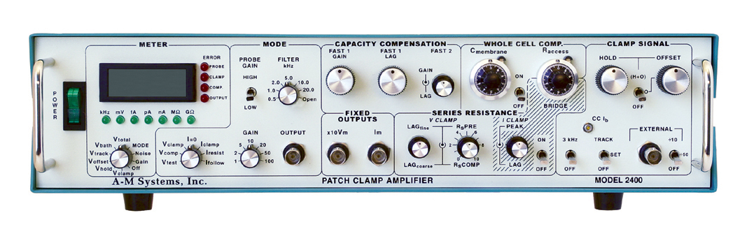
Model 2400 Patch Clamp Amplifier
A full-featured, manually operated patch-clamp amplifier suitable for extracellular and intracellular recording. Allows working with patch electrodes on individual channels and with the whole cell. A budget-friendly solution for small laboratories.
- Overview
- Specifications
- Links
LOW NOISE, FULL-FEATURED
Designed for voltage clamping on individual channels or whole cells using patch electrodes
A low-noise, fully functional patch clamp amplifier called the Model 2400 is made for voltage clamping with patch electrodes on individual channels or entire cells. Additionally, its layout enables quick intracellular current clamp measurements using tipped electrodes.
Key Features
- Patch clamp amplifier with full function for whole cells and patches
- True current clamp has a 200 kHz bandwidth and is 100 percent stable.
- Headstage with switchable dual resistive feedback
- Series resistance, capacity, and whole-cell compensation
- Low-Pass Bessel filters with 4 poles
- Test signals generated internally
- The majority of the front panel controllers have telegraph outputs.
- Independent circuits for hold, offset, and tracking
- Displays cell currents, voltages, and command potentials
Since the gain is influenced in part by the value of the resistor in the headstage, it is possible to tailor the amplifier current gain to your experimental needs by choosing one of the three dual resistive feedback probes that are offered. The three available heastages are 1 G/10 M, 10 G/10 M, and 10 G/100 M. Because feedback resistors come in a broad variety, currents can be recorded with outputs ranging from 1 mV/nA to 10 mV/fA. Each device comes with a 100 M/10 G version of the standard probe, though different values can be chosen.
The Model 2400 contains a voltage follower in the probe, which is unique compared to other patch clamp amplifiers. Due to the lack of instability, this amplifier can function as a real fast current clamp amplifier. Flexible signal conditioning is provided via a four pole low pass Bessel filter integrated into the system. It is possible to fine-tune capacity compensation to practically remove all electrode-induced transients. Whole cell compensation that has been calibrated makes it simple to see membrane capacitance and access resistance.
The internal architecture of the model 2400 incorporates a variety of command potentials, including an automatic tracking command to zero the membrane current, human offset and holding potential controls, and an easily visible digital display. Any signal source can be used in conjunction with an external command input that has various scaling factors to handle more complex signals. The genuine RMS noise of the amplifier and experimental setup, the cutoff frequency of the low pass filter, and the overall gain of the amplifier plus probe may all be accurately measured using a digital meter.
The researcher can introduce either or both predictive and corrective compensation from zero to 100% using series resistance compensation. The delicate control offered by fine and coarse controls for lag helps to reduce oscillation brought on by compensation that is near to 100%. When the bridge balance is applied, there are separate compensation settings for removing transients observed during current clamp studies.
The analog voltage equivalents of the front panel settings for error circumstances, amplifier mode and gain, Cmembrane, RMS noise, and low pass filter cut-off value are provided by the telegraph outputs. The front panel settings of the Model 2400 can be automatically recorded by your system software thanks to these telegraphs.
The Model 2400 Patch Clamp Amplifier from A-M Systems can be used as a cost-effective teaching rig in your graduate classes or as a top-notch research amplifier in your lab.
The Model 2400 comes with:
- Hardware for rack mounting and an operator's manual
- Model Cell
- Rack mounting equipment
You can also visit site of the manufacturer.

We are a distributor of A-M Systems, LLC in Ukraine, Kazahstan and Europe