/ Catalog / Microinjection and Perfusion Systems / npi MVCS Iontophoresis
- Our e-mail:
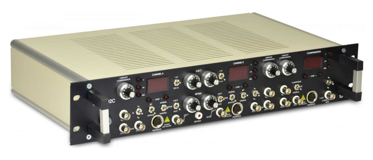
MVCS – Iontophoresis
There are 2 versions of npi MVCS Iontophoresis: 1) A very rapid version (under 1 ms) with capacity compensation and electrode resistance testing; 2) A slower variant lacking capacity compensation and electrode resistance testing.
- Overview
- Specifications
- Links
Advantages of the MVCS
- Utilize charged substances with exceptional temporal and spatial accuracy.
- Focus on individual synaptic boutons – local resolution approximately 1 µm³.
- High voltage pulses in the sub-millisecond range – the quickest iontophoretic system available on the market.
- Prevent leakage of substances by employing the hold/retain current settings.
- ±45V or ±150V voltage range with a highly precise current pump.
- Balance channel featuring automatic counter-current application to prevent specimen charging.
- Manage the MVCS with any data acquisition system.
Iontophoresis Amplifier
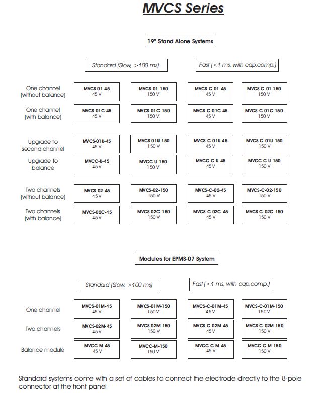
Essentially, MVCS systems are offered in:
- A very rapid version (under 1 ms) with capacity compensation and electrode resistance testing.
- A slower variant lacking capacity compensation and electrode resistance testing.
Fast systems (MVCS-C-02C) come with headstages, ground connector, power cord, and user manual.
Slower systems (MVCS-02C) include connectors for electrode and ground connections, a power cord, and a user manual (excluding headstages).
Standard voltage ranges are ±45 V or ±150 V, with additional ranges available upon request.
NOTE: All MVCS systems can also be provided as one-channel versions, which can be upgraded to two channels. Additionally, all versions can be ordered without a balance channel.
For further information, please reach out to us.
Refer to the “Specifications” tab for all available options. Customized configurations are feasible; please contact npi electronic.
The MVCS is also offered as a module for the EPMS-07 system.
Features
- One or two channel versions (upgrade available)
- Time resolution: as low as 100 µs
- Spatial resolution: as low as 1 µm
- Simulation of synaptic events, ideal for receptor density mapping.
- Automated balancing of iontophoretic current (optional)
- Currents ranging from tens of pA to µA.
- High voltage, high-speed current source.
- Automated electrode resistance testing.
Selecting a Model
The rapid systems are equipped with a headstage for each channel. This feature facilitates the integration of capacitance compensation circuitry and resistance measurement. If application pulses are required in the range of a few milliseconds or even less for highly focused applications, this system is the preferred option.
The slower system lacks headstages and capacitance compensation. It is appropriate when timing is not critical (e.g., bulk loading).
The balance channel injects an equal amount of current into the sample as the application channel(s) – but with opposite polarity. This ensures that the overall charge of the sample remains constant. This is particularly beneficial when conducting parallel recordings, where DC shifts could compromise the measurement (e.g., patch clamp).
For 98% of experiments, the 45 V system is entirely adequate. The 150 V system should only be utilized if large currents are required and feasible. It is important to remember that even npi’s instruments cannot circumvent Ohm’s law.
Example: 150 V applied to a 1 MΩ electrode will produce a current of 150 µA.
Specifications of the MVCS
MODE of operation:
- set with two toggle switches, EJECT / RETAIN / AUTO switch enables manual or TTL
- controlled operation
- SET / OPERATE switch connects automatically electrode outputs to an internally grounded load, to make possible well defined presetting (SET position)
- COMPENSATE / OFF / EXTERN switch (balance unit), selects compensation signal or connects
- balance module to external signal source (additional channel).
HEADSTAGES:
- Size (approx.): Standard 70x30x25 mm, holding bar diameter 8 mm, length 150 mm (±15 V, ±45 V), optional: 100x50x20 mm (± 150V) or 225x40x60mm (± 225V).
- Electrode connector: BNC connector, (headstage with driven shield also available).
- Ground connector: 2.4 mm connector.
- Electrode output: floating current source, output impedance >1012 Ω
ELECTRODE RESISTANCE TEST:
- 1 mV / MΩ at the voltage monitor Vel / 10, obtained by application of square current pulses,
- ±10 nA from built-in pulse generator.
EJECT: ten-turn control, switch selected range max. 1 µA / 100 nA.
RETAIN: ten-turn control, max. 100 nA.
CAPACITY COMPENSATION: range 0 30 pF, ten-turn control.
MAXIMUM CURRENT:
- 150 nA (±15 V), 450 nA (±45 V standard voltage), 1.5 µA (±150 V) into 100 MΩ load. Other ranges available on request.
- OUTPUT CURRENT POLARITY:
- selected by INVERTED / NORMAL toggle switch.
- BALANCE OUTPUT (MVCS-X-02C-45, MVCC):
- inverted sum of all currents, sensitivity 1 µA / V, for connecting external balance module.
TTL INPUT (AUTO mode): LO = RETAIN, HI = EJECT, isolated, Rin > 5 kΩ
ANALOG INPUT: sensitivity 100 nA / V, Rin > 100 kΩ, range ±10 V.
CURRENT MONITOR: sensitivity 100 nA / V, Rout = 250 Ω, not isolated.
VOLTAGE MONITOR: Vel / 10, Rout = 250 Ω, not isolated.
DISPLAY:
- current XXXX nA, balance current XX.XX µA, voltage XXX.X V, REL XXXX MΩ,
- separate displays for each channel, displayed value is set by a three position toggle switch.
- OVER LEDs:
- activated 10 % below maximum current.
POWER REQUIREMENTS: 115 / 230 V AC, 45 – 60 W.
DIMENSIONS: 19″ cabinet, 19“ (483 mm), x 10″ (250 mm) x 3.5″ (88 mm)
Ordering Information
- MVCS-01-45 MVCS-01-45V 19″ Iontophoresis System
- MVCS-01C-45 MVCS-01C-45V 19″ Iontophoresis System (with balance)
- MVCS-01U-45 2nd Channel Upgrade f. MVCS-01-45 System (19″)
- MVCC-U-45 Balance Upgrade f. MVCS-45 System (19″)
- MVCS-02-45 MVCS-02-45V 19″ Iontophoresis System
- MVCS-02C-45 MVCS-02C-45V 19″ Iontophoresis System (with balance)
- MVCS-01-150 MVCS-01-150V 19″ Iontophoresis System
- MVCS-01C-150 MVCS-01-C-150V 19″ Iontophoresis System (with balance)
- MVCS-01U-150 2nd Channel Upgrade f. MVCS-01-150 System (19″)
- MVCC-U-150 Balance Upgrade f. MVCS-150 System (19″)
- MVCS-02-150 MVCS-02-150V 19″ Iontophoresis System
- MVCS-02C-150 MVCS-02-C-150V 19″ Iontophoresis System (with balance)
- MVCS-C-01-45 MVCS-C-01-45V 19″ Iontophoresis System
- MVCS-C-01C-45 MVCS-C-01C-45V 19″ Iontophoresis System (with balance)
- MVCS-C-01U-45 2nd Channel Upgrade f. MVCS-C-01C-45
- MVCC-C-U-45 Balance Upgrade f. MVCS-C-45 System (19″)
- MVCS-C-02-45 MVCS-C-02-45V 19″ Iontophoresis System
- MVCS-C-02C-45 MVCS-C-02C-45V 19″ Iontophoresis System (with balance)
- MVCS-C-01-150 MVCS-C-01-150V 19″ Iontophoresis System
- MVCS-C-01C-150 MVCS-C-01-C-150V 19″ Iontophoresis System (with balance)
- MVCS-C-01U-150 2nd Channel Upgrade f. MVCS-C-01C-150 System (19″)
- MVCC-C-U-150 Balance Upgrade f. MVCS-C-150 System (19″)
- MVCS-C-02-150 MVCS-C-02-150V 19″ Iontophoresis System
- MVCS-C-02C-150 MVCS-C-02-C-150V 19″ Iontophoresis System (with balance)
- MVCS-01M-45 MVCS-01M-45V Module for EPMS-H
- MVCS-01M-150 MVCS-01M-150V Module for EPMS-H
- MVCS-02M-45 MVCS-02M-45V Module for EPMS-H
- MVCS-02M-150 MVCS-02M-150V Module for EPMS-H
- MVCC-M-45 Balance Module f. MVCS-45 System (EPMS-H)
- MVCC-M-150 Balance Module f. MVCS-150 System (EPMS-H)
- MVCS-C-01M-45 MVCS-C-01M-45V Module for EPMS-H
- MVCS-C-01M-150 MVCS-C-01M-150 V Module for EPMS-H
- MVCS-C-02M-45 MVCS-C-02M-45V Module for EPMS-H
- MVCS-C-02M-150 MVCS-C-02M-150V Module for EPMS-H
- MVCC-C-M-45 Balance Module f. MVCS-C-45 System (EPMS-H)
- MVCC-C-M-150 Balance Module f. MVCS-C-150 System (EPMS-H)
- MVCS-HS-150 Headstage for MVCS-150 Systems
- MVCS-HS-45 Headstage for MVCS-45 Systems
- MVCS-EH Standard Micro Electrode Holder
You can also visit site of the manufacturer.

We are a distributor of NPI Electronic GmbH in Estonia, Latvia, Lithuania and Ukraine, Kazahstan and Europe