- Our e-mail:
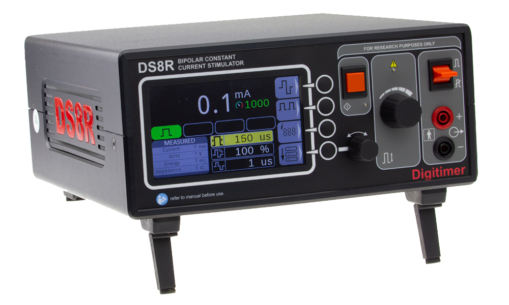
DS8R Biphasic Constant Current Stimulator
The DS8R biphasic DC stimulator supports a current range of 0 to 1000 mA, in 0.1 mA increments, and voltages up to 400 V; pulse duration range 50-2000 ?µs; Designed for human and animal research.
- Overview
- Specifications
- References
- Links
FEATURES
- 0.1 mA increments from 0 to 1000 mA, from up to 400 V
- Current Output Limit (user set between 10 mA and 999 mA)
- Pulse durations between 50 and 2000 µs
- Triggering up to 10 kHz is possible with special edition firmware that is optional. Inquire with us for further information.
- Charge-balanced symmetric or asymmetric biphasic output
- Developed for use in human research
A brand-new multi-mode, discrete pulse, constant current stimulator called the DS8R Biphasic Constant Current Stimulator has been developed for use in human research studies that stimulate nerve and muscle using surface electrodes. It has a high compliance voltage and can be activated by a front-panel "single-shot" button, contact closure foot/hand switch, or input that is TTL compatible. Although the DS8R has an output range of 0-1000 mA in 10 µA steps (from 400 V) and can generate monophasic or biphasic pulses of up to 2ms duration, the actual current achieved will be constrained by a pulse energy limit of 300mJ per pulse and the skin/electrode resistance. The new DS8R has capabilities that enable external "on the fly" modification of stimulus pulse parameters.
Optional Firmware for High Frequency (10kHz) Stimulation
Researchers who want to stimulate at frequencies higher (10kHz) than those allowed by the basic device can also get a special edition firmware. With the use of this optional firmware, researchers studying spinal cord injuries can use transcutaneous spinal cord stimulation (TSCS) protocols that were motivated by "Russian" stimulation techniques to assess how the procedure affects function recovery.
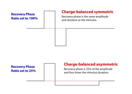
Biphasic Charge-balanced Output
Two pulse modes on the DS8R Biphasic Constant Current Stimulator allow for stimulation with either monophasic or biphasic rectangular pulses. The DS8R also supports both symmetric and asymmetric charge-balanced stimuli in biphasic mode thanks to the installation of a programmable stimulus/recovery phase amplitude ratio. Biphasic charge-balanced stimulation provides some benefits over monophasic stimulation, including the prevention of potentially hazardous electrochemical alterations that can take place under stimulation sites and the observed improvement in patient comfort during prolonged treatment. The recovery phase ratio can be changed in 1% steps from 10% to 100%. When seen below, while the ratio is 100%, the two phases have the same duration and amplitude. However, as the ratio decreases below 100%, the recovery phase's amplitude decreases while its duration increases to maintain charge balancing.
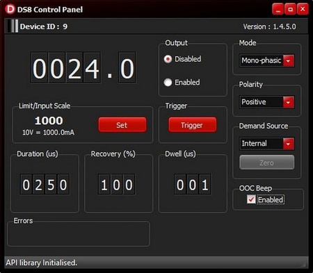
External Control Capabilities – Software (via USB) and Analogue Voltage Input
With the introduction of the DS8R, the desire of researchers to modify stimulus parameters (current and duration) throughout a stimulation paradigm has become a reality. The DS8R can be fully controlled by the front panel to function as a stand-alone isolated stimulator, but settings can also be changed using (provided) Windows PC control software via a USB link. More importantly, this software includes an API that enables the operator to build control using unique or commercially available software packages, for CED Signal/Spike2, Python, or Matlab. It also provides a Virtual Front Panel for the stimulator.
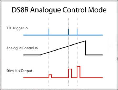
An analogue voltage input (BNC) is located on the back of the DS8R and can be used to more easily control the pulse current amplitude. As each trigger input is identified using this way of control, the DS8 monitors the voltage applied at this input (0–10V) and modifies the stimulus current accordingly with this voltage. It should be noted that the control voltage signal only serves to proportionally represent the output stimulus current; it does not specify the shape of the output pulse.
With Demanding Human Research Applications in Mind
Although the DS8R is acceptable and secure for use in human research applications, Digitimer is not pursuing medical device certification for the DS8R since its maximum pulse energy of 300mJ exceeds the 50mJ cap set by international standards for clinical evoked-potential stimulation devices.
The instrument was used in these investigations:
- No increased suggestibility to placebo in functional neurological disorder.
Huys, A. M. L., Beck, B., Haggard, P., Bhatia, K. P., & Edwards, M. J.
(2021). European Journal of Neurology, ene.14816. - Not as ???blurred??? as expected? Acuity and spatial summation in the pain system.
Adamczyk, W. M., Szikszay, T. M., Kung, T., Carvalho, G. F., & Luedtke, K.
(2021). Pain, 162(3), 794??“802. - Effects of post-exercise blood flow occlusion on quadriceps responses to transcranial magnetic stimulation.
Latella, C., Pinto, M. D., Nuzzo, J. L., & Taylor, J. L.
(2021). Journal of Applied Physiology, japplphysiol.01082.2020.
You can also visit site of the manufacturer.

We are a distributor of Digitimer, ltd. in Estonia, Latvia, Lithuania and Ukraine, Kazahstan