- Our e-mail:
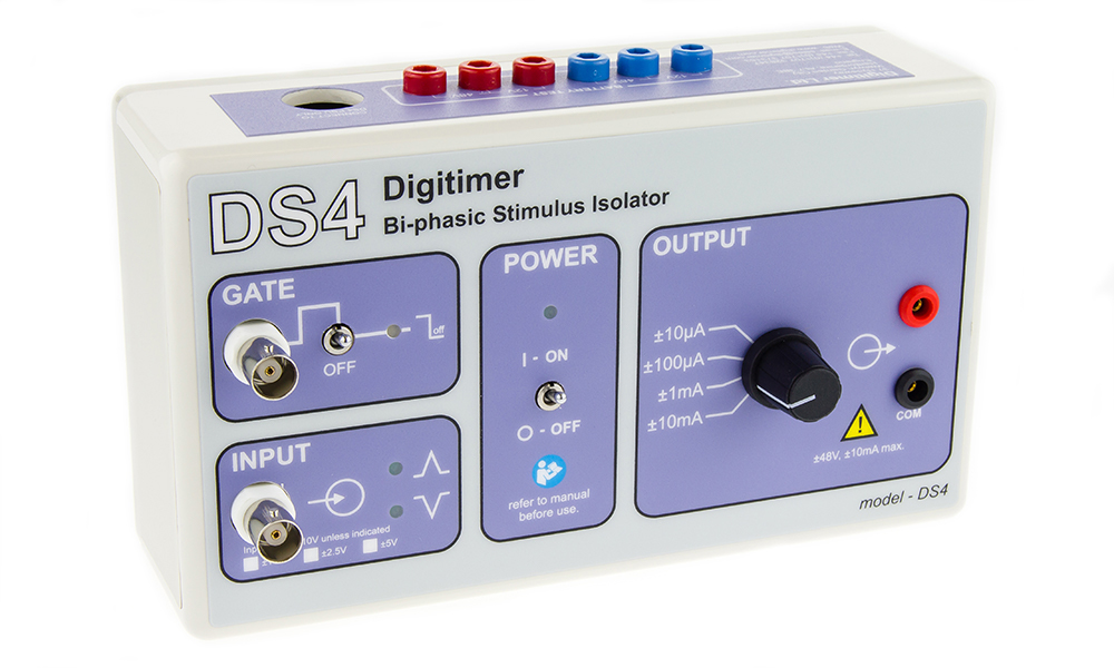
DS4 Bi-Phasic Current Stimulator
The Digitimer DS4 Biphasic Current Stimulator is capable of delivering a biphasic isolated DC stimulus in response to an external command voltage signal supplied by a computer DAC via software.
- Overview
- Specifications
- Links
FEATURES
- Designed for use on animals or in vitro
- Software defined waveforms are possible with external voltage control.
- Low noise isolated constant current output
- Zero crossing distortion is minimized
- Leak currents are considerably reduced by an inactivity sensor.
- Test sockets for batteries
The DS4 Bi-Phasic Current Stimulator was created in answer to the demands of life scientists who needed a stimulus isolator that could produce a bi-phasic isolated continuous current stimulus in response to an external command voltage signal, which was supplied by a computer DAC via software. The NL512 Biphasic Buffer and NL800A Stimulus Isolators from NeuroLog System already fulfill this demand, but the DS4 Bi Phasic Stimulator is the first standalone device from Digitimer to do so. Low noise is a fundamental necessity in animal or in vitro electrophysiological applications, which is where the DS4 is intended for use. It is not safe for humans to use the DS4.
Low Noise Isolated Output Stage
The stimulation voltage in the low noise, optically isolated output stage of the DS4 is generated by two banks of batteries, while the control circuitry is powered by a DC supply. The DS4 is not a conventional triggered stimulator; rather, it generates a proportional constant current stimulation from a biphasic voltage waveform. This means that the DS4 is capable of producing monophasic or biphasic stimuli with waveforms of any shape, including sine waves, rectangular pulses, and even completely arbitrary waveforms. The DS4 has two input sockets: the main INPUT socket, which receives the voltage command signal, and the optional GATE input, which can be used as a "soft on/off switch" to activate and deactivate stimulation using TTL logic.
Stimulate with Arbitrary Shaped Waveforms
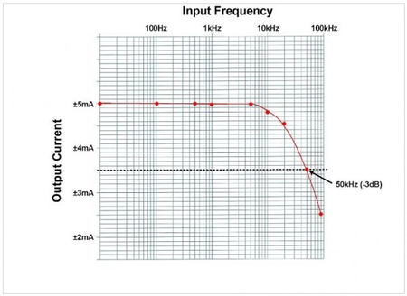
The stimulator has specific frequency response characteristics that define how well it can follow fast changing or high frequency command inputs because the DS4 functions like a voltage to current amplifier. The DS4's frequency response plot is displayed below, showing how well it performs when a ±5V input is applied and the device is set to have a maximum input range of ±10V, a maximum output range of ±10mA, and a load resistance of 1kohm. The graph demonstrates that the predicted DS4 output is consistent up to 5 kHz, whereas the -3dB roll-off occurs at 50 kHz.
Unique “Inactivity Sensor” Prevents Unwanted DC Stimulation
Small offsets or noisy baseline signals from the DACs used to drive them might cause unintended battery drain or, what's worse, low amplitude stimulation in stimulators that employ an external voltage source to establish a stimulus waveform. The DS4 monitors the input voltage using a unique "inactivity sensor," which turns off the DS4 output if the voltage drops to less than 0.15% of the full scale value (in the negative or positive directions) for a user-selectable timeout of 200ms, 500ms, 1s, or 2s. This "inactivity sensor" minimizes battery consumption and harmful "leak currents" during sparse stimulation while retaining low levels of zero crossing distortion for repeating waveforms, unlike other devices that only ever produce an output when the input voltage exceeds a threshold value.
There are four different settings for the inactivity sensor timeout, and they can be changed using on-board jumpers that are located inside the battery compartment. It is crucial to remember that when the DS4 is initially utilized after a period of inactivation, the inactivity sensor will cause a very minor "glitch" in the stimulus waveform. This is such that no output may occur until the command input voltage surpasses 0.15% of the whole scale, which the inactivity sensor prevents.
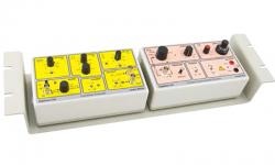
The opto-isolated stimulation voltage source for the DS4 Stimulator is provided by easily available/cheap batteries, while the input control circuitry is powered by an external DC power supply. The DS4 can be installed in a 19-inch rack mounting frame (D121-11) that can accommodate up to two DS2As, DS3s, DS4s, or DG2As.
ACCESSORIES
Supplied
Power Supply Adaptor
Mains Lead
Operator’s Manual
One set of batteries
Pair of output plugs (NL985P)
Recommended
DS4-BATT – Set of Replacement Batteries
Additional NL985P Output Plugs
You can also visit site of the manufacturer.
These products may be of your interest

We are a distributor of Digitimer, ltd. in Estonia, Latvia, Lithuania and Ukraine, Kazahstan