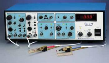
Duo 773 Electrometer
Two-channel low-noise amplifier for intracellular microelectrode registration. Features capacitance compensation, signal filtering, current injection, overvoltage alarm, bridge balance, etc.
- Overview
- Specifications
- Links
A Two-Channel Intracellular Amplifier for Comparative and Multiple Research
- Two channels for intracellular or differential ISE
- DC current generator integrated with external control input
- Built-in low pass filter
- Circuitry using a bridge to balance the electrode voltage
- "Tickler" circuit
- Each channel has built-in test ports.
- Output offset controls and dual capacitance compensations
- Includes two probe headstages, typically one high- and one low-impedance headstage.
Benefits
- Single-ended, dual-channel recording
- Differential recording
- Electrode voltage drop is eliminated via a bridge circuit.
- Either channel could be given a low pass filter.
- The intracellular ISE can be employed with very high impedance channels.
Applications
- Utilizing sharp micropipettes for intracellular electrophysiology
- Intracellular recording in brain slices
- Brain and spinal cord in vivo intracellular recording
The Duo773 includes built-in active filtering and distinct negative capacity controls that enable exact balancing of time constants for artifact-free differential measurement for intracellular dual or differential research. includes two probe headstages, 1015 and 1011 probes, for signal monitoring from KCl-filled electrodes as well as ion-specific microelectrodes.
Headstage for Proper Placement
Two tiny active probes with gold plating and epoxy seals can be placed right at the measuring location. The probes accept plug-in microelectrode holders with Ag/AgCl electrochemical half-cells. By covering the microelectrode holder at the probe's end with the driven guard shield that is included, stray capacitance can be decreased.
Compensation for Capacity
Both Channel A and Channel B have electrode shunt compensation capacities of up to 50 pF and 10 pF, respectively.
Circuit Tickler for Penetrating Cells
Cell penetration is aided by a tickler circuit. The oscillations' frequency and amplitude can be adjusted to account for variations in cell size or membrane thickness. The momentary switch, a foot switch, or the application of a signal to the remote tickler input can all be used to regulate the length of the tickle.
Active Filters
A -40 dB/decade active filter's low pass settings let you adjust the cutoff frequency from 1 to 30 kHz. Filtering can be applied to either probe outputs or bridge outputs.
Injection of Current
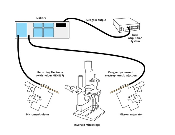
By sending a command signal to the stimulus input connection, Channel B can inject current through the microelectrode. The probe will produce a constant current copy of the input signal as its output. There are two available current delivery ranges: 50 nA and 500 nA, or an external source. This source can be utilized as a holding current for microiontophoresis as well as a means of supplying hyperpolarizing currents to stabilize the potential of the cell membrane.
Bridge Balance
Subtracts the extra electrode voltage caused by the recording micropipette's current delivery. Two ranges can be used to balance electrode resistances up to 1000 MΩ. The front panel output connectors x10 or x50 provide access to the balanced signal.
Independent Outputs
Each probe's output on the Duo773 is independent of gain filtering and balancing. The Duo773 also features a 10x and 50x output for simple interaction with the majority of data collecting programs.
Typical Setup

You can also visit site of the manufacturer.


